Whenever a modular system is turned on there's a current spike upon startup that will momentarily influence the PSU output and can take up to a couple seconds for the PSU to stabilize to it's stated specifications. PSUs can also have some delay between their power lines where one polarity is provided prior to the second one. They also commonly have a ramp like startup. All this is common and normally not a problem. While most modules are fine with this situation, there are others that can suffer from this and in a worst case scenario won't startup correctly. Some modules can also be sensitive to the timing of the ±12v, some may require both to arrive at the same time others won't start if -12v arrives prior to the +12v, etc.
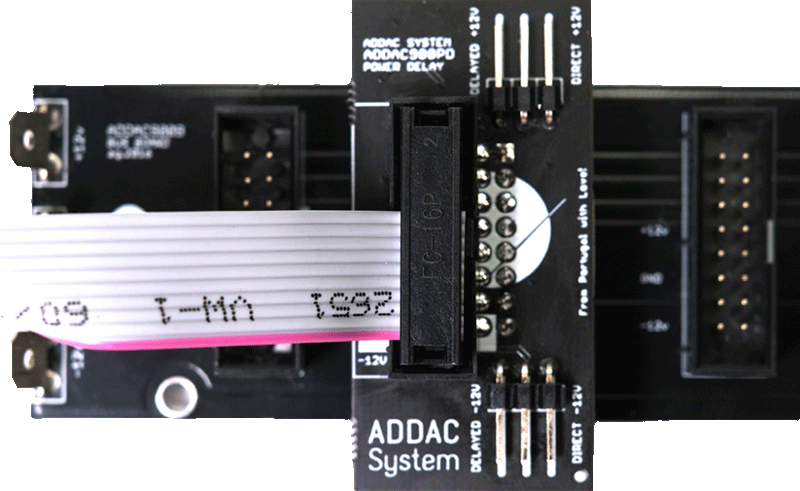
This small board allows to time the deployment of power to a specific module, it can delay each power line independently by 3 seconds, meaning that after powering up your modular it will wait for 3 seconds until it will provide power to the specific module connected to it. This delay time can also be customized by the user replacing a couple capacitors.
Using this small board with more sensitive modules allow them to power up at a time past the initial spike and where the PSU is already stable and it will guarantee that the ±12V is delivered at exactly the same time.
Besides this very technical use there are other creative and useful uses, for example plug it to those specific modules that "drive" your patch, like a sequencer or a clock and have them power up later so that other modules have time to start up and stabilize before starting up the clock. Go even deeper in this idea and have diferent 900PDs with diferent capacitors that will allow you to "program" a sequential module power up, useful for generative patches that run on a power timer in exhibitions and galleries.
One more useful hack is to use it in those cases where your frame won't power up due to the initial current "spike", making it going over its limits and trip the protection mechanism failing to startup. The usual "hack" is to unplug one or two modules allowing it to power up and then connect the extra modules in. ***Warning*** power up issues like these simply means your PSU is close to its maximum and the pcb shouldn't be used as a permanent fix and we advise upgrading the PSU. However it will make it easier in that situation where you add one last minute module for that gig in a few hours and that extra module trips the psu protection, then as a temporary hack the pcb will make it easier for the frame to power up at the gig.
There are 2 sets of jumpers to independently set the power line to be delayed, -12V, +12V or both.
This pcb will be plugged onto your busboard and, in turn, allow a ribbon power cable to be connected to it.
There are 2 models ADDAC901PDO for Old style Busboards and ADDAC901PDN for New style Busboards
DISCLAIMER: Both the ADDAC901PDO and the ADDAC901PDN are not to be used with modules that require external +5V supply.
DIY-Kit-Type:
SMD-Kit-1. This is a Do-It-Yourself kit, not an assembled module. The kit includes all parts to build the module. All SMD parts are pre-soldered, only trough-hole parts to solder. For build guide, more info, videos etc. please check the buttons below.
| DIY Level: | Easy |
|---|
ADDACSystem, Lda.
Av. Eng. Arantes e Oliveira 5, S/Lj E
1900-221 Lisbon
Portugal
addac@addacsystem.com
Product Safety Information
Eurorack DIY Kits
Important Notice & Intended Use
Please read this safety guide before installation or use. This kit is intended for adult users experienced in electronics and modular synthesis. Assembly, including soldering, is required. Proper testing and installation are essential to ensure safe and functional operation. The completed module is intended for installation in a Eurorack-compatible synthesizer system powered by ±12V and +5V.
General Warnings
1. Electrical Hazards:
• Ensure the power supply matches the module’s specified voltage and current ratings (refer to the product manual). Incorrect voltage can damage the module and pose a safety risk.
• Never connect or disconnect the module while the Eurorack system is powered on.
• Wrong polarity can damage your module or system. Make sure the module is connected with correct polarity.
2. Heat Generation:
• The module may generate heat during operation. Ensure proper ventilation within your Eurorack case to prevent overheating.
3. Sharp Edges:
• The module’s faceplate and components may have sharp edges. Handle with care to avoid cuts or scratches.
4. Small Parts:
• Contains small parts that could cause a choking hazard. Keep away from children and pets.
5. Compatibility:
• This module is designed specifically for Eurorack-compatible systems. Connecting it to non-compatible systems may result in damage or malfunction.
Assembly Requirements
• Soldering skills are required to complete the module.
• Ensure a clean, well-lit and ventilated workspace free of flammable materials during assembly.
• Use appropriate tools and safety equipment, such as eye protection.
Testing
• Test the module thoroughly for shorts or incorrect assembly before powering it in your Eurorack system. When the unit has malfunctions due to incorrect assembly, the entire Eurorack system might be damaged. It's a good idea to test it in a separate case with only that single module.
• Use a multimeter or other appropriate tools to confirm proper functionality.
Installation and Use
• Mount securely in a Eurorack case using the provided screws.
• Use only the included or manufacturer-recommended power cable.
• Connect only when the power is off.
• Follow the module's user guide for instructions on operation. Do not exceed the input/output limits specified.
Responsibility
Users are solely responsible for proper assembly and testing. Contact manufacturer support for assistance if needed.
Environmental Safety
• Dispose of the module, its components, and packaging in accordance with local electronic waste regulations.
Liability Disclaimer
• The manufacturer or distributor is not responsible for any injury, damage, or malfunction resulting from improper installation, use, or modification of this product.
Contact Information
For further assistance, contact the manufacturer (you'll find the info under each product in our shop) or our shop support team at:
Tech Creation Lab Leipzig UG (haftungsbeschränkt)
Nonnenstrasse 19, 04229 Leipzig, Germany
support@exploding-shed.com
ADDAC develops advanced instruments for sonic expression.
We started back in 2009 with an ambition to explore the potential crossover between analog synthesizers and computers. Because our first creations sparked a lot of attention, we decided to work hard and put them in your hands.
Today our product line is focused on a new breed of hybrid synths, that make use of the best of both the digital and analog worlds. We've grown to be able to reach thousands of enthusiastic clients, friends and collaborators. Always looking into conceptualizing and developing the most exquisite instruments, we hope you're able to join and share this passion with us.
Our solutions can be found in many personal studio throught the world, owned by musicians in several planes of stardom. We especially appreciate seeing them being used in a very wide range of musical genres.
Login


